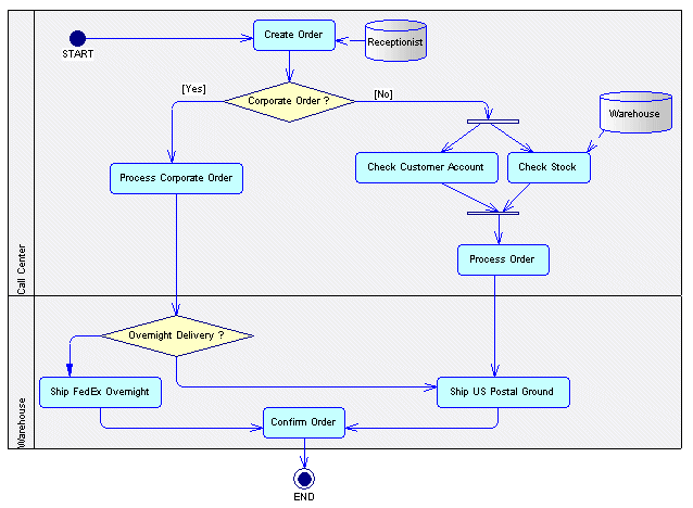
A business process diagram (or process flow diagram) provides a graphical view of the control flow (the sequence of execution) or data flow (the exchange of data) between processes at any level in your system.
- Trace the choreography of processes through flows from one or more starts through a sequence of sub-processes, decisions, synchronizations, and resources to one or more ends. The parent process being analyzed in the diagram must wait for the end of all its sub-processes before it terminates.
- Avoid unassigned tasks and duplicated assignments by placing processes in organization unit swimlanes (see Attaching Processes to Organization Units).
- Analyze how data flows through a system via:
- Message formats on flows – To define exchange formats for large amounts of data that transit between processes, usually defined by a DTD or an XSD (see Message Formats (BPM)).
- Data on Flows - To model data (which can be associated with objects defined in a data model or OOM) without specifying its format (see Data (BPM)).
- Data CRUD – To specify the actions (create, read, update and delete) that a process can perform on data (see Data and Resource CRUD Matrices).
Note: The data flow diagram helps you analyzing data exchange between processes (see Data Flow Diagram (DFD)). -
Model the implementation of processes (see Implementing Processes)
A business process diagram can be created directly under the model root, or inside a package or decomposed process.
In this example, the processing of an order proceeds differently depending on whether or
not it is a corporate order. Both possible paths are reunited in the Confirm Order
process:
|
Object |
Tool |
Symbol |
Description |
|---|---|---|---|
|
Process |

|
 |
Task to perform (see Processes (BPM)). |
|
Organization unit |

|
 |
Organization, service or person that is responsible for a process (see Organization Units ( BPM)). |
|
Flow |

|
 |
Path of the control flow between processes (see Flows (BPM )). |
|
Decision |

|
 |
Decision to take when several flow paths are possible. Only one path will be triggered at execution time (see Decisions (BPM )). |
|
Synchronization |

|
 |
Enables synchronization of flows between two or more concurrent actions or allows the design of a split (see Synchronizations (BPM )). |
|
Start |

|
 |
Starting point of the processes described in the choreography diagram (see Starts and Ends (BPM )). |
|
End |

|
 |
Termination point of the processes described in the choreography diagram (see Starts and Ends (BPM )). |
|
Message format |
None |
 |
Format definition of data exchanged between processes (see Message Formats (BPM)). |
|
Data |
None |
None |
Piece of information exchanged between processes (see Data (BPM)). |
|
Resource |

|
 |
Storage unit of abstract data circulating within the model, which is accessed by a process to perform actions (see Resources (BPM)). |
|
Resource flow |

|
 |
Access of a process to a resource (see Resource Flows (BPM)). |
