A data flow diagram (DFD) is a graphical representation of the flow of data through an information system without any indication of time. DFDs are commonly used to provide an initial top-down analysis of a system, identifying the processes to be carried out and the interactions and data exchanges between them. DFDs can be either logical, providing an implementation-independent description of the system, or physical describing the actual entities (devices, department, people, etc.) involved.
| Tool | Symbol | Description |
|---|---|---|

|
Gane & Sarson: Yourdon: |
Process - An activity that transforms or manipulates input data to produce output data (see Processes (BPM)). Flows from processes can go to external entities, data stores, split/merges, or other processes. The Data tab in the process property sheet displays the process CRUD accesses to data. Note: To choose a notation, select and select the appropriate Data Flow Diagram
Notation.
|
 
|

|
Flow - Oriented link that conveys data between processes, external entities, and data stores and represents data in motion. Flows are based on standard flows (see Flows (BPM )) with a Flow stereotype. Flows to or from data stores are based on standard resource flows (see Resource Flows (BPM)), and must be created with the Resource Flow tool. A flow cannot directly link two data stores or two external entities. The Data tab in the flow property sheet displays the data transported by the flow. |

|
Gane & Sarson: Yourdon: |
Data store - Location where data resides permanently or temporarily and represents data at rest. Data stores respond to requests for storing and accessing data, but cannot initiate any actions, and are based on standard resources (see Resources (BPM)) with a Data Store stereotype. Flows to data stores represent write, update, or delete access, and flows from data stores represent read access. |

|

|
External entity - A person, organization, or system outside the system being modeled that sends data to or receives data from the system. Flows from external entities cannot directly access data and must pass through processes. External entities are based on standard organization units (Organization Units ( BPM)) with an External Entity stereotype. |

|

|
Split/Merge - Splits a flow into two or more flows or merges multiple flows into a single flow. Split/merges are based on standard synchronizations (see Synchronizations (BPM )) with a Split/Merge stereotype. A split/merge can, for example, split a complex packet of data into more elementary packets, and send them to different processes or duplicate data to send to different processes, or alternatively merge multiple data packets together for onward transmission. |
| None | None |
Data - Conceptual information exchanged between the other objects (see Data (BPM)) You can associate the data analyzed in a DFD with conceptual, logical, and physical data models and object-oriented models (see Linking Data with Other Model Objects). |
Analysts typically begin with a system context DFD to show the interactions between the
system as a whole and external entities. In the following example, the Great
Care Society process interacts with the Donors,
Bank, Members, and Prospective
Members external entities:
You can decompose processes in a DFD (see Decomposing Processes), and PowerDesigner initializes the
subdiagram with all the objects that link to the process being decomposed (external
entities, data stores, and shortcuts to processes as necessary). Such
balancing helps ensure that all the flows to and from the process being
decomposed are preserved at the next level of decomposition. When the Great Care Society process is decomposed its diagram is
initialized with the four external entities:
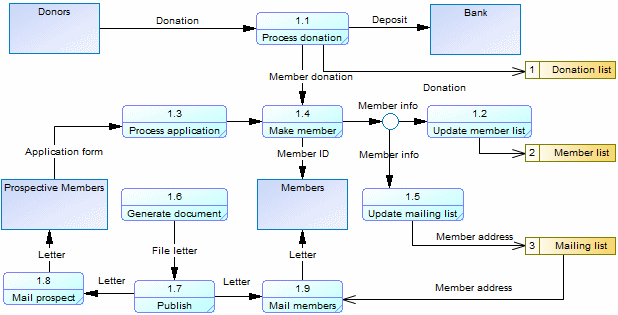
The diagram is enriched to show the sub-processes that handle donations,
deposits, and correspondence, and the data stores that they interact with:
To test balancing, select , and select the balancing checks under the Flow and Resource Flow objects.
When using the default Gane & Sarson methodology, processes and data stores are
automatically numbered. As you decompose your processes, child processes inherit the
number ID of their parent process so that the first child of top level process 1 is
numbered 1.1, and the first child of this process is numbered 1.1.1. This numbering
scheme enables you to easily identify the lineage of a process at any level of
decomposition and provides a convenient way to reference processes and data stores by
numbers instead of sometimes long or complex names:


