To view or edit a component's properties, double-click its diagram symbol or Browser or list entry. The property sheet tabs and fields listed here are those available by default, before any customization of the interface by you or an administrator.
The General tab contains the following properties:
|
Property |
Description |
|---|---|
Name/Code/Comment |
Identify the object. The name should clearly convey the object's purpose to non-technical users, while the code, which is used for generating code or scripts, may be abbreviated, and should not normally include spaces. You can optionally add a comment to provide more detailed information about the object. By default the code is generated from the name by applying the naming conventions specified in the model options. To decouple name-code synchronization, click to release the = button to the right of the Code field. |
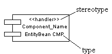
Stereotype |
Extends the semantics of the object beyond the core UML definition. You can enter a stereotype directly in this field, or add stereotypes to the list by specifying them in an extension file. You can modify an existing stereotype or create a new one in an object language or extension file. |
|
Type |
Specifies the type of component. You can choose between a standard component (if no specific implementation has been defined) or a specific component, such as EJB, JSP, Servlet or ASP.NET (see Web Services). To display the type of a component, select and select the Type option in the component category.  Whenever you change the type of a component after creation, the modification triggers a conversion from one type to another: all relevant interfaces, classes, and dependencies are automatically created and initialized. Such a change will affect some property sheets, the Check Model feature, and code generation. For example, if you convert a standard component to an EJB Entity Bean, it will automatically generate a Bean class and a primary key class of the EJB, as well as home and component interfaces. If you convert an EJB to a standard component, the classes and interfaces of the EJB are preserved in the model. |
|
Transaction |
Used for a component with transactional behavior. |
|
Class diagram |
Specifies a diagram with classes and interfaces linked to the component, which is automatically created and updated (see Creating a Class Diagram for a Component). |
|
Web service |
Indicates that the component is a Web service. |
Keywords |
Provide a way of loosely grouping objects through tagging. To enter multiple keywords, separate them with commas. |
Interfaces Tab
Each component uses one or several interfaces. It also uses or requires interfaces from other components. These interfaces are visible entry points and services that a component makes available to other software components and classes. If dependencies among components originate from interfaces, these components can be replaced by other components that use the same interfaces.
The Interfaces tab lists interfaces exposed and implemented by the component. Use the Add Objects tool to add existing interfaces or the Create an Object tool to create new interfaces for the component.
Component interfaces are shown as circles linked to the component side by an horizontal or a vertical line:

The symbol of a component interface is visible if you have selected the Interface symbols display preference from . The symbol of an interface can be moved around the component symbol, and the link from the component to the interface can be extended.
If you are working with EJB, some of the interfaces have a special meaning (local interface, remote interface, etc...). For more information, see Defining Interfaces and Classes for EJBs.
Classes Tab
A component usually uses one implementation class as the main class, while other classes are used to implement the functions of the component. Typically, a component consists of many internal classes and packages of classes but it may also be assembled from a collection of smaller components.
The Classes tab lists classes contained within the component. Use the Add Objects tool to add existing classes or the Create an Object tool to create new classes for the component.
Classes are not visible in the component diagram.
The following tabs are also available:
Components - lists the child components of the component. You can create components directly in this tab.
-
Operations - lists the operations contained within the interfaces associated with the component. Use the filter in the toolbar to filter by a specific interfaces.
-
Ports - lists the ports associated with the component. You can create ports directly in this tab (see Ports (OOM)).
-
Parts - lists the parts associated with the component. You can create parts directly in this tab (see Parts (OOM)).
-
Files - lists the files associated with the component. If files are attached to a component they are deployed to the server with the component (see Files (OOM)).
-
Related Diagrams - lists and lets you add model diagrams that are related to the component (see Core Features Guide > Modeling with PowerDesigner > Diagrams, Matrices, and Symbols > Diagrams > Specifying Diagrams as Related Diagrams).