To view or edit an actor's properties, double-click its diagram symbol or Browser or list entry. The property sheet tabs and fields listed here are those available by default, before any customization of the interface by you or an administrator.
Implementation Classes Tab
An actor can be a human being (person, partner) or a machine, or process (automated system). When analyzing what an actor must do, you can identify the classes and interfaces that need to be created for the actor to perform his task, and attach them to the actor. The Implementation Classes tab lists the classes and interfaces used to implement the actor. The following tools are available:
For example, an actor Car could be implemented by the classes Engine and Motorway.
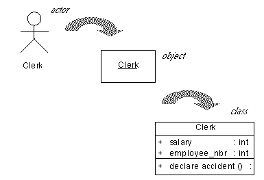
Conceptually, you may link elements even deeper. For example, a clerk working in an insurance company is represented as an actor in a use case diagram, dealing with customers who declare a car accident.
The clerk actor becomes an object in a communication or sequence diagram, receiving messages from customers and sending messages to his manager, which is an instance of the Clerk class in a class diagram with its associated attributes and operations:

Related Diagrams Tab
The Related Diagrams tab lists diagrams that help you to further understand the actor. Click the Add Objects tool to add diagrams to the list from any model open in the workspace. For more information, see Core Features Guide > Modeling with PowerDesigner > Diagrams, Matrices, and Symbols > Diagrams > Specifying Diagrams as Related Diagrams.


