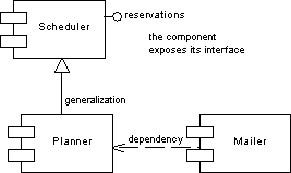
A component diagram is a UML diagram that provides a graphical view of the dependencies and generalizations among software components, including source code components, binary code components, and executable components.
For information about Java- and .NET-specific components, see Working with Java and Working with VB .NET.
The following example shows relationships between components in a showroom reservation system:

Component diagrams are used to define object dependencies and relationships at a higher level than class diagrams.
Components should be designed in order to be reused for several applications, and so that they can be extended without breaking existing applications.
You use component diagrams to model the structure of the software, and show dependencies among source code, binary code and executable components so that the impact of a change can be evaluated.
A component diagram is useful during analysis and design. It allows analysts and project leaders to specify the components they need before having them developed and implemented. The component diagram provides a view of components and makes it easier to design, develop, and maintain components and help the server to deploy, catalog, and find components.