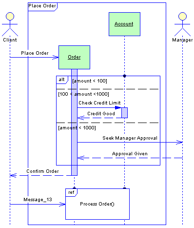
A sequence diagram is a UML diagram that provides a graphical view of the chronology of the exchange of messages between objects and actors for a use case, the execution of an operation, or an interaction between classes, with an emphasis on their chronology.
You can use one or more sequence diagrams to enact a use case or to identify all the possibilities of a complex behavior.
A sequence diagrams shows actors, objects (instances of classes) and the messages sent between them. It conveys the same kind of information as a communication diagram, except that it concentrates on the chronology of messages passing between the objects in place of their structure.
By default, PowerDesigner provides an "interaction frame", which surrounds the objects in the diagram and acts as the exterior of the system (or part thereof) being modeled. Messages can originate from or be sent to any point on the frame, and these gates can be used in place of actor objects (see Messages and Gates). You can suppress the frame by clicking , selecting the Interaction Frame category and deselecting the Interaction Symbol option. For detailed information about using display preferences, see Core Features Guide > The PowerDesigner Interface > Diagrams, Matrices, and Symbols > Display Preferences.
One of the major advantages of a sequence diagram over a communication diagram is that you can reference common interactions and easily specify alternative or parallel scenarios using interaction fragments. Thus, you can describe in a single sequence diagram a number of related interactions that would require multiple communication diagrams.
In the following example, the Client actor places an order. The Place Order message creates an Order object. An interaction fragment handles various possibilities for checking the order. The Account object and Manager actor may interact with the order depending on its size. Once the Confirm Order message is sent, the Process Order interaction is initiated. This interaction is stored in another sequence diagram, and is represented here by an interaction reference:

Analyzing a Use Case
A sequence diagram can be used to refine a use case behavior or description. This approach is useful during requirement analysis because it may help identify classes and associations that did not emerge at the beginning.
You can formalize the association between the use case and the sequence diagram by adding the diagram to the Related Diagrams tab of the property sheet of the use case.
It is often necessary to create several diagrams to describe all the possible scenarios of a use case. In this situation, it can be helpful to use the sequence diagrams to discover all the pertinent objects before trying to identify the classes that will instantiate them. After having identified the classes, you can then deduce the associations between them from the messages passing between the objects.
Analyzing a Class Diagram
Building a sequence diagram can also be the opportunity to test a static model at the conception level; it may represent a scenario in which classes from the class diagram are instantiated to create the objects necessary to run the scenario.
It complements the class diagram that represents the static structure of the system by specifying the behavior of classes, interfaces, and the possible use of their operations.
A sequence diagram allows you to analyze class operations more closely than a communication diagram. You can create an operation in the class of an object that receives a message through the property sheet of the message. This can also be done in a communication diagram, but there is more space in a sequence diagram to display detailed information (arguments, return value, etc) about the operation.
When you use the Merge Models feature to merge sequence diagrams, the symbols of all elements in the sequence diagram are merged without comparison. You can either accept all modifications on all symbols or no modifications at all.